


View the complete article here.
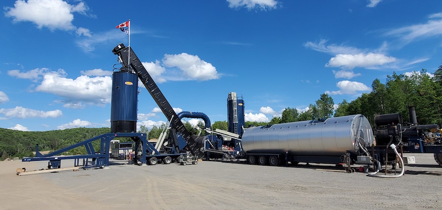
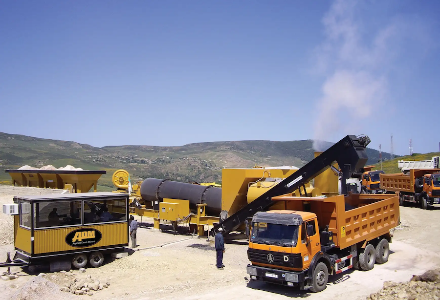
Some companies, like ADM Asphalt Drum Mixers, offer portable hot mix asphalt (HMA) plants that can be setup quickly and run by just two workers – a plant operator and a load operator. In this article, we walk you through the basic steps on how to set up a portable asphalt plant.
HMA Plant Set Up Overview
There are five general steps to setting up your portable asphalt plant:
- Read the Manual.
- Site Preparation.
- Equipment Placement.
- Electrical and Plumbing Installation.
- Equipment Testing and Calibration.
An HMA Expert
For this article, we consulted ADM Asphalt Drum Mixers. Asphalt Drum Mixers has been manufacturing asphalt plants and components since 1974. So they kinda know what they’re talking about.
Read the Manual
We know – you just want to get mixin’ as soon as possible. But even if you’ve setup an HMA portable plant before, there are differences between manufacturers. And, hey, a refresher course can only help. So crack open that manual and give it a thorough read.
Site Preparation
First be aware of what’s around the site. Be a good neighbor to the people who occupy the homes and businesses around your HMA portable plant. Wind direction and traffic will impact them the most. But they also affect plant operations. Foundations, if needed, and stockpile location are also important aspects of site preparation.
Wind Direction. Note in which direction the wind generally blows from. The idea is to reduce dust which can gum up equipment over time. As ADM explained to us, “That’s why you should have a dust control program which includes frequent watering of bare drives and lots. You’ll want to frequently do inspections and maintenance. And proper PPE should be worn at all times.”
Truck and Equipment Traffic. Your goal is to create a traffic flow pattern to reduce traffic for the surrounding community and increase efficiency within the plant. You want to eliminate blind spots (use those big mirrors to help drivers see around blind spots you can’t remove). You also want to reduce the risk of collisions by minimizing cross traffic.
Foundations. You may use full-width sand shoes, wood or steel cribbing, large stones, or concrete pads. This varies depending on what supports the manufacturer provides, as well as soil conditions and how long you plan to remain on the site. Some portable asphalt plants — such as ADM’s EX Series counterflow plant – allow you to setup directly on the ground in most situations. Your goal here is to setup quickly while still maintaining solid support.
Stockpiling. Place the stockpiles in a location where the loader operator and delivery vehicle can easily access them, but also reduces cross traffic. Allow enough space between the stockpiles to keep the material separated. You can achieve this by placing bulkheads between them or storing the material in bins.
Erect the Equipment
We layout each step in setting up your portable asphalt plant’s equipment. This is to give you a good idea of what’s involved, but always follow the instructions provided by the manufacturer. When in doubt, contact the manufacturer or equipment dealer. Let’s begin.
Silo
If the portable silo is not self-erecting, such as ADM’s 75 Ton Capacity SES75 Self-Erecting Silo, then a crane will be required to lift it and the drag slat conveyor into place. In some cases, these items are pre-assembled. Note that you should use the bolts provided by the manufacturer.
- If not already done by the manufacturer, place the silo on its side and install the legs.
- If rigging allows it, install bolt on handrails or bolt-on batch hopper.
- You can install the ladder-cage assembly can before or after the silo is positioned.
- Tighten and secure all hardware.
- Connect the lift cable slings to the lifting eyes on the silo top.
- Lift the silo and place on the foundation plates.
- Weld and/or bolt all four legs to the foundation plates.
- Remove the cable hooks and release the crane cables.
- Rig, lift, and mount the drag cradle, batch hopper, and hand railing.
- Bolt down to silo.
- Remove the cable hooks and release the crane cables.
Drag Slat Conveyor
- In preparing to lift the drag slat conveyor, position the unit so that only a single lift is required to place it directly into the foundation position.
- Lift the drag slat conveyor with the lifting eyes on both ends of the conveyor. Note that the top end is heavier.
- Lift the drag slat conveyor, position the head section on the saddle, and place the drag base on the foundation plate.
- Weld and/or bolt the drag base to the foundation plate.
- Remove the cable hooks and release the crane cables.
- Install or secure any drag supports that may be included.
- Install any items such as bypass chute, guard rails, stairs, etc. that will require the use of the crane.
- Remove the cable hooks and release the crane cables.
Drum Unit
Keep the area cleared until the drum unit is pinned and secured. Use the foundation prints to find the measurements for positioning the unit.
- Measure and mark the position of the unit from the drag chute.
- Maneuver the truck rig and drum unit over the exact position so that the discharge point lines up to the drag slat conveyor receiving point.
- Lift and level the unit into place using the crank-down or hydraulic legs that came with the unit.
- If the equipment has fixed legs, manual placement and shimming to level the unit may be needed.
- Secure and pin all support legs to the frame and bolt and/or weld the legs to the foundation plate, if needed.
- Install the receiving chute on the drag slat conveyor and the discharge chute on the drum unit.
- Install and/or fold down the receiving chute or slinger conveyor, breeching box, hand railing platforms, ladders, and any other required items.
Weigh Conveyor
The measurements for positioning the weigh conveyor can be found on the foundation prints.
- Measure and mark the position of the unit from the receiving chute on the dryer or fast conveyor.
- Maneuver the truck rig and conveyor close to position.
- Unfold or lift the weigh conveyor head unit into working position.
- Maneuver the truck rig and conveyor unit so that the material will fall into the center of the receiving chute.
- Unbolt or position the scalping screen from the conveyor. Ensure that the scalping screen does not touch the weigh conveyor.
Refer to the foundation prints to find the measurements needed to position the aggregate feed system unit.
- Measure and mark the position of the unit from the weigh conveyor.
- Maneuver the truck rig and bin unit close to position.
- Unfold the collecting conveyor and place it at the correct angle to match the weigh conveyor.
- Install the conveyor supports and / or chains to hold the conveyor in position.
- Maneuver the truck rig and bin unit into position so that when the collecting conveyor discharges onto a screen, it discharges onto the top one-third section of the screen cloth.
- Lift and level the bins using the crank or hydraulic legs provided, and bolt and/or weld the legs onto the foundation pads if using.
- Install or position into place any ladders, platforms, bin dividers, bin extensions, and other required equipment.
- If equipped, install or position the folding bulkheads and tie down cables into working position so that the ramps can begin to be filled.
Baghouse
Refer to the foundation prints to find the measurements for positioning the baghouse unit.
- Measure and mark the position of the unit from the drum unit.
- Maneuver the truck rig and baghouse unit into position.
- Install or position ductwork on both the drum unit and baghouse. A crane may be required. Seal all duct unions.
- Install or position into place any ladders, platforms, railing, airlocks, blowers, dust augers, stacks, and other required equipment.
Asphalt Storage Tank
You will find the measurements for positioning the asphalt storage tank in the foundation prints.
- Measure and mark the position of the AC tank unit from the drum unit.
- Maneuver the truck rig and conveyor unit close to position.
- If using an ADM-supplied asphalt pump and tank, mount the asphalt pump on the back of the asphalt tank. ADM tanks have the asphalt pump mounted at the factory when they are portable.
- The asphalt tank and pump should be mounted as closely as possible to the AC injection lines.
- Ensure that the asphalt tank is properly supported.
Fuel Tank
Find the measurements for positioning the fuel tank in the foundation prints.
- Measure and mark the position of the unit from the center line of the drum unit.
- Maneuver the truck rig and tank unit close to position.
- The fuel tank must be at least 50 feet from the burner.
- The fuel tank should be equipped with a fuel filter.
- The supplied pump must also have a filter.
- All lines must be sized to the recommendations of the burner manufacturer.
RAP System
Locate the measurements for positioning the RAP system unit in the foundation prints.
- Measure and mark the position of the unit from the receiving chute on the recycle collar.
- Maneuver the truck rig and conveyor unit close to position.
- Unfold or lift the conveyor head unit into working position.
- Maneuver the truck rig and the conveyor unit so that the material will fall into the center of the receiving chute.
- Lift and level the RAP bin(s) using the crank or hydraulic legs provided, and bolt and/or weld the legs onto the foundation pads, if using.
- Install or position into place any ladders, platforms, bin dividers, bin extensions, and other equipment required.
- If equipped, install or position the folding bulkheads and tie down cables into working position so that the loading ramps can begin being filled.
Install Electrical Cables and Plumbing
You may want to use a licensed electrician and licensed plumber for this part of the portable HMA plant setup.
Electrical
- Move the generator into position.
- Install and connect the main power cable and test the generator for proper voltage.
- Beginning with the farthest cable, lay out the high voltage motor wire along provided cable trays, and plug into the main MCC, typically at the control room.
- Secure the cable along the way with proper wire ties.
- Continue until all motors are plugged into their proper outlets.
- Lay out the 110V control cables along the cable trays securing them so that they do not lie on top of the high voltage wires.
- Secure the cable along the way with proper wire ties.
- Continue until all control cables are plugged into their proper outlets.
- Lay out the low voltage signal cables along the provided cable trays assuring that they do not lie alongside the high voltage cables, crossing only when necessary.
- Secure the cable along the way with proper wire ties.
- Continue until all signal and low voltage cables are plugged into their proper outlets.
- Some cables may need to be hardwired.
Plumbing
- Simplify plumbing connections for the asphalt and fuel tanks using hoses with quick connections.
- Hot oil-heated flex hose packages with quick connections (available from ADM) can provide quick connections from the asphalt pump to the plant.
- Fuel hoses with spill-proof quick disconnects can make fuel connections safe, quick, and easy (available from ADM).
- Always check all plumbing for leaks, wear, and damage to avoid unwanted spills.
- If your plant is not equipped with quick connections, use the plumbing diagrams provided by the manufacturer to connect the equipment.
Test and Calibrate
The following steps may need to be performed by an OEM certified technician or a licensed electrician.
- With all breakers in the “off” position, check power at the top of the main breaker.
- If power is correct, turn on main breaker and check power at the bottom of the main.
- Continue this for all breakers in the circuit to assure all connections and power are correct.
- After assuring power is correct, continue testing by turning all motors and checking rotations.
- Once all electrical is tested, perform calibrations of the asphalt pump, weigh conveyor, cold feed bins, surge system scales, and other systems such as level indicators, temperature sensors, and others.
- Follow the manufacturer’s instructions for proper testing of your HMA plant’s systems.
Conclusion
Our step-by-step instructions should give you a good feel for what’s involved in setting up a portable asphalt HMA plant. Of course, the instructions in your portable HMA plant’s manual from the manufacturer take precedence to our instructions. Our advice related to being a good neighbor, implementing a dust control system, and using high-quality PPE should be followed for setting up and running any type of HMA plant.
View the complete article here.
What are the key steps involved in setting up a portable asphalt plant?
The process includes reading the manual, site preparation, equipment erection, electrical and plumbing installation, and equipment testing and calibration.
How can I efficiently prepare the site for a portable asphalt plant, considering factors like wind direction and traffic impact?
Site preparation involves being aware of wind direction for dust control, optimizing traffic flow for efficiency, and considering foundation needs and stockpile placement for easy access.